This was my entry for the 2014 European Freedom Design Contest organised by EEWeb, Digi-Key, Freescale and ARM. To my great pleasure this entry was selected First Place of Phase 2! (the Grand Prize). Some of the design tools that had to be used have gone offline since then.
The goal is to create an application using a Freescale Freedom board, draw its schematics at Scheme-It, do a PCB design at PCBweb and program it with mbed.
Looking at the Freedom boards I was quickly seduced by the FRDM-K64F based on the Freescale K64FN1M0 ARM Cortex-M4. This is a processor that I have never used before, so this was a good opportunity to get started. As a project I decided to try to port my NXP’s LPC1347 ARM Cortex-M3 based music synthesizer that I completed recently (open source, open hardware), the idea being that the K64F’s DSP capabilities, its whopping 1 MB flash memory (eight times the size of my Cortex-M3) and its higher clock speed should allow for much more sophisticated sound algorithms. Furthermore, it features an I²S port, which will be good for streaming samples to a quality digital-to-analog converter (DAC).
Every project needs a name, or at least a working name, so I baptised this project the Kinetisizer.
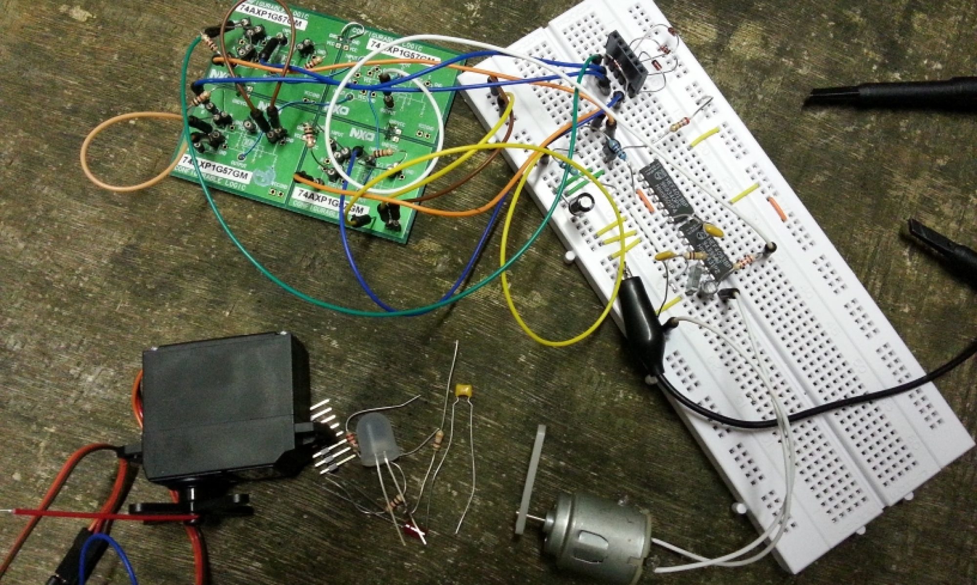
Since time is limited I cut the project in three main stages where the first stage is to get the current Cortex-M3 design working on the Cortex-M4 (hardware version MK1). In this design the audio samples use a high-frequency PWM signal (instead of I²S) that is filtered by a fifth order Chebychev filter. The second stage (hardware version MK2) would be the replacement of the PWM signal by the I²S module. In the third stage things should get really interesting as this is the stage where sound algorithms will be added and improved.
Scheme-It
For this contest it was required to draw the schematic at Scheme-It and so I did. Even though I had never used this tool before I managed to get the drawing done rather quickly and I found the result graphically quite pleasing. OK, it could have been nicer if I had taken the trouble to use multiple sheets, but I didn’t because I had more important things to do and not a lot of time left.
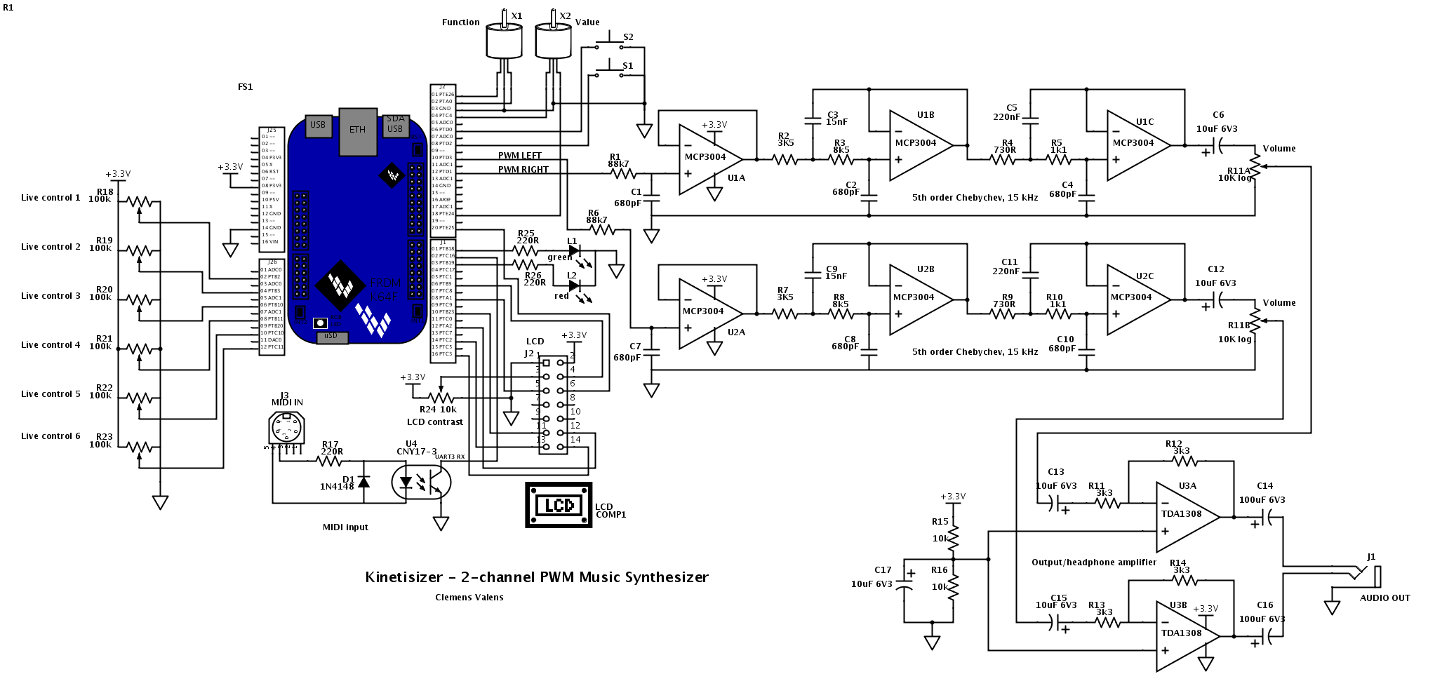
Below is the iframe that should show the circuit diagram at the Scheme-It website, but in case it doesn’t work I also included a PNG of the drawing.
About the circuit
Because the FRDM-K64F board is mbed enabled, the circuit is layed out to make it mbed compatible too.
The blue block in the schematic is of course the Freedom board. On the right of it the three opamps of U1 and its surrounding resistors and capacitors form a fifth order Chebychev anti-aliasing filter with a cut-off frequency of 15 kHz. This frequency may seem low but is high enough for acceptable audio quality while keeping the PWM sample rate reasonably low. An identical circuit for a second audio channel is formed around U2. The two channels are connected to the pins PTD1 and PTD3 that have PWM capabilities (according to mbed).
The outputs of the filters pass through a volume potentiometer before going to headphones amplifier U3. J1 is the synthesizer’s audio output.
At the top of the drawing we have two rotary encoders (Function and Value) and two pushbuttons (integrated in the rotary encoders) that form the main controls of the synthesizer. These are used to setup the basic parameters of a sound and of the synthesizer. They rely on pull-up resistors inside the microcontroller.
The six potentiometers on the left of the Freedom board are the live controls that allow modifying selected sound parameters on the fly during a performance. They are connected to the analog inputs according to mbed.
The red/green bicolor LED (L1 and L2) serves to indicate the operating mode of the potentiometers (there are two modes so that they can control up to twelve parameters).
A liquid crystal display (LCD) is available for showing parameter values to the user. It is connected in such a way so that the I²S interface of the K64F remains free since it will be needed in hardware version MK2.
U4, an optocoupler, is the Musical Instrument Digital Interface (MIDI) input. An external MIDI keyboard should be connected to this input in order to play the synthesizer. UART3 is used to receive the MIDI data on the mbed RX input.
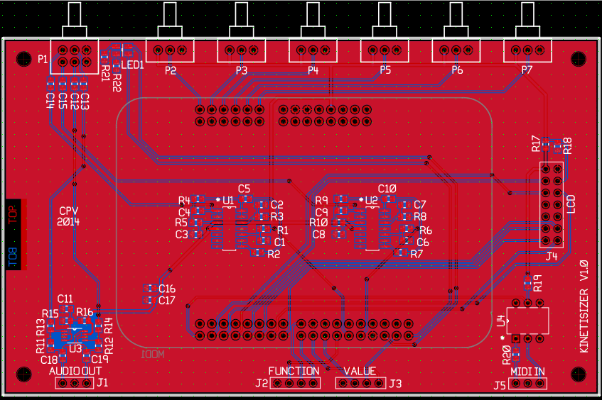
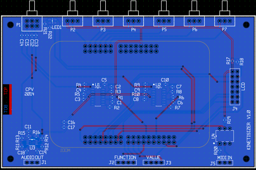
PCBWeb Designer
Before I could get started on the software I needed to get the PCB design done because PCBs take time to manufacture and ship. For the PCB design I had to use the on- and offline tool PCBWeb Designer. This again was a new tool for me and although it hasn’t (yet?) reached the ripeness of say Altium Designer I did get my board design done. The main inconvenience was that I had to draw my circuit diagram all over again. Maybe there is an import function somewhere to get it from Scheme-It, but I didn’t find it. Not only is redrawing a lot of work, it is also error prone. Unfortunately the component libraries turned out to be of little use which made me lose a lot of time.
PCBWeb Designer however does have one good thing going for it: the PCB database is a human readable XML file. Editing the PCB in a text editor got me quickly out of several holes that otherwise would have required redrawing large parts of the PCB to correct mistakes that I had made because I was too unfamiliar with the tool.
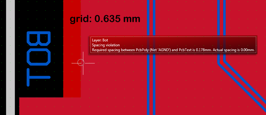
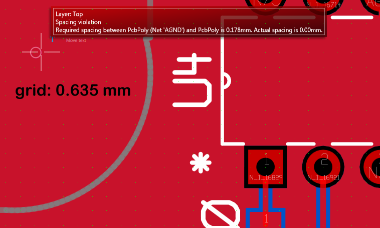
Finally the result looks OK except for two DRC errors that seem to be bugs. One is a text too close to polygon error even though they are miles apart. The other is a polygon too close to polygon problem which seems to be random.
You can also download the design files below.
- PCBWeb design file (XML file, right click to download).
- PCBWeb circuit diagram as PDF.
- Gerber files.
The Freedom board is supposed to go under this PCB. To use Arduino speak, this PCB is a kind of shield. The potentiometers can go either side, but bottom side will be more compact.
mbed
I have worked with mbed before so I know more or less how it works, but it has evolved quite a bit since the last time I looked at it.
Since the software was written for another hardware platform with another microcontroller it has to be ported. Luckily the sound engine doesn’t need a lot of work because it is mostly platform independent (except for the PWM part) but everything that relies on the specific peripherals of my Cortex-M3 (GPIO, PWM and timers) will need porting. Because the Freedom board runs at 120 MHz or so it makes a rather easy target. Thanks to its speed and power it allows me to use all the high-level mbed libraries without worrying. This saved me a huge amount of boring MCU datasheet and user-manual reading. With a couple of calls to DigitalIn and DigitalOut I could replace all the original GPIO calls from the Cortex-M3 library. Perfect for reading pushbuttons and rotary encoders and for controlling LEDs.
Instead of studying the ADC peripheral before reading the position of the six potentiometers I could now simply use the AnalogIn class.
The mbed community has provided a cool FastPWM class compatible with the K64F, another great time saver.
The original design had an LCD with I2C interface that I replaced in this design by a classic 4-bit parallel interface. Again the mbed environment has all I need to get the display going.
Finally, I replaced my lowish-level systick routine by the Ticker class.
My current port (more than 30 source files, not counting the header files) compiles without errors and warnings. You can download the project here (about 22 MB). I also published it on mbed but I am not sure if that was a good idea as I didn’t have the time to test it properly. Use at your own risk 🙂
To be continued…
Presented above is the first stage of the porting of my ARM Cortex-M3 based PWM music synthesizer to an ARM Cortex-M4 based I²S music synthesizer. My original design is open source and open hardware, the new design is too. The original design was created using free versions of commercial tools (Eagle from CADsoft and LPCXpresso from NXP), the new design was done in on-line tools that are free and target the open source community (SchemeIt, PCBWeb Designer and mbed). During this project it has become clear that on-line tools have become very capable and can be used to create and share complicated hardware with embedded software designs.
The remaining steps to complete this project are:
- Testing of the MK1 prototype hardware
- Extensive testing of the new MK1 firmware
- Replace the PWM DACs by a two-channel (or more) I²S DAC (MK2)
- Improve the sound engine to fully profit from the increased processing power
Stay tuned!
P.S. All the design files are open source and open hardware. Please respect the licenses that can be found in the source code.