
I just found an error in the drawings 9.2 and 9.3. Indeed, the power pins of the DCF77 module have been inverted. The correct connections are:
1 – GND
2 – VCC
3 – TXD
4 – TXD inverted
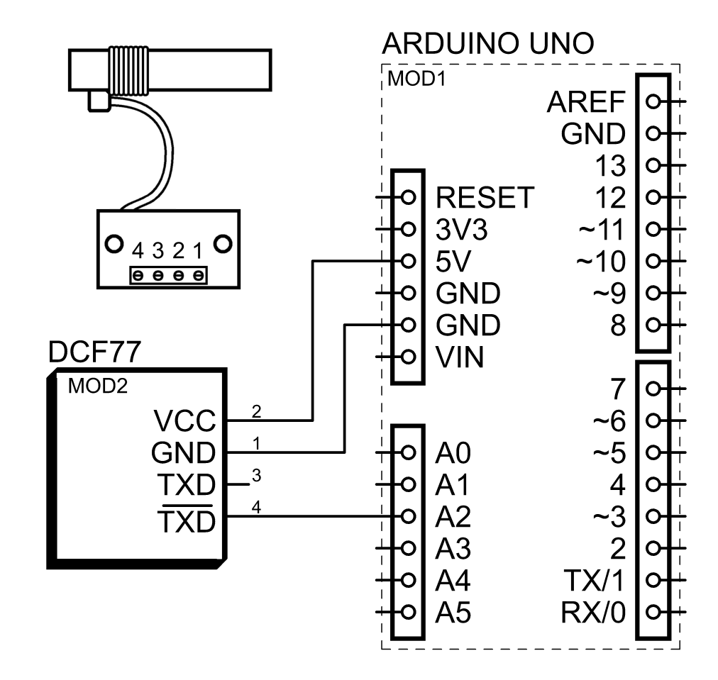
Figure 9-2 corrected: 1 – GND, 2 – VCC
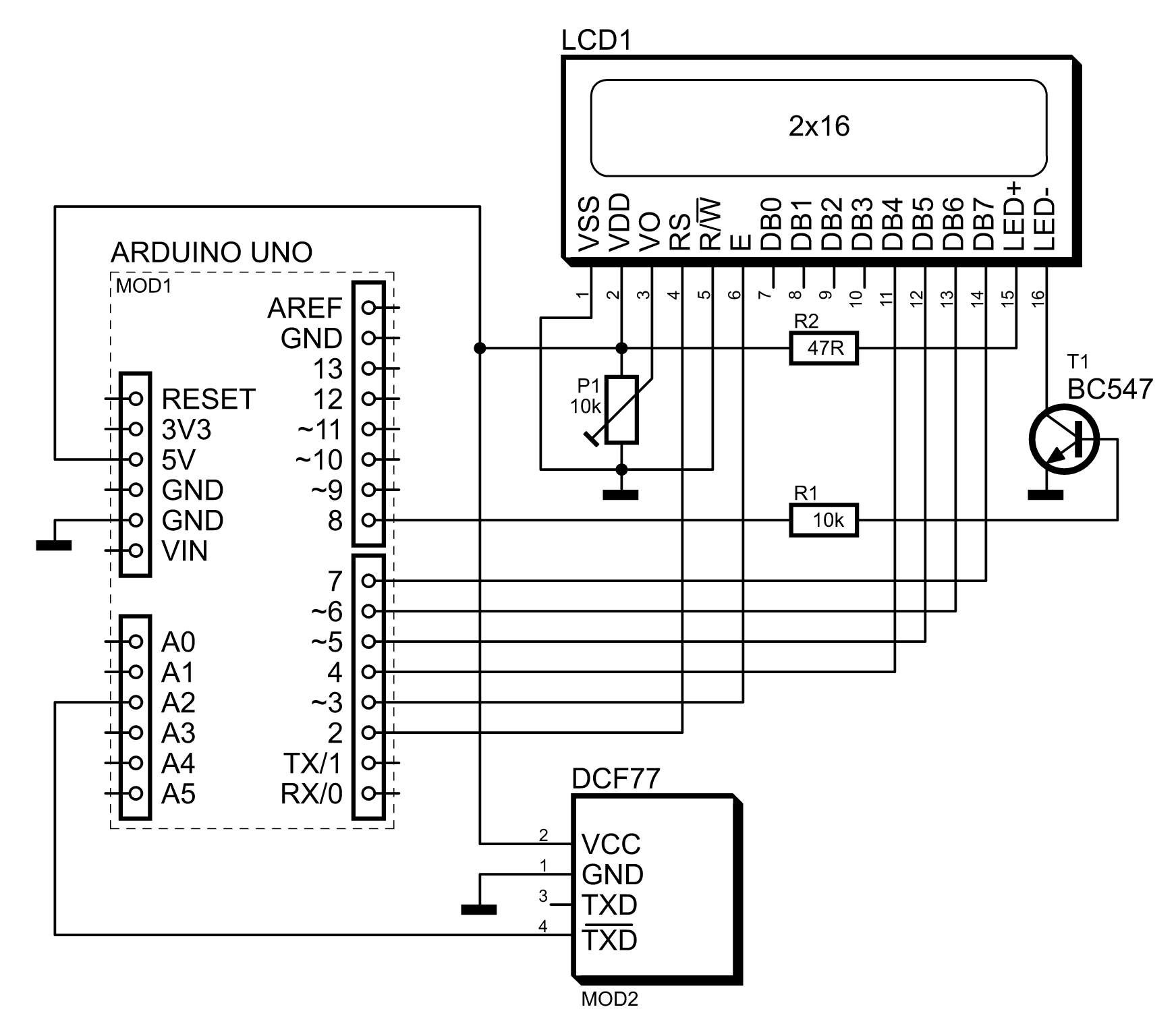
Figure 9-3 corrected: 1 – GND, 2 – VCC
This error will (hopefully) be corrected in the next print of the book.
Sorry for this.