This is my entry for NXP’s AXP Logic 2014 Design Contest. The goal was to design something funky using one or more 74AXP1G57GM configurable logic chips and, if needed, other parts.
To my great pleasure this entry was selected as the Grand Prize Winner!
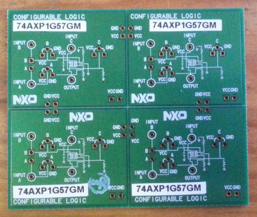
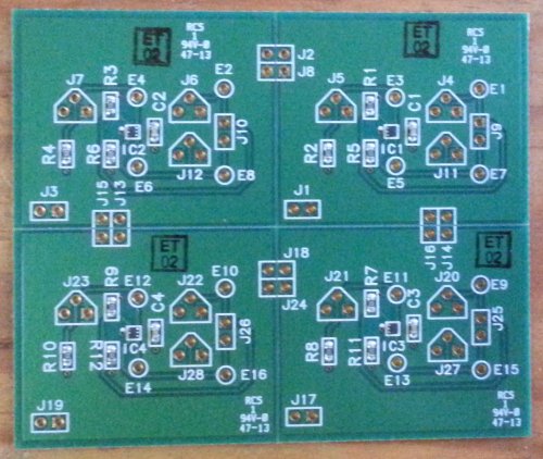
I applied for a free board and received one some two weeks later. The board actually consisted of four identical boards, each with a 74AXP1G57GM chip and a 4k7 pull-down resistor on every input. Per input three holes are provided for easy connection, the output has only one point of connection. The chip itself is so small that you can hardly see it. The circuit diagram is printed on the back of the PCB.
Inside the chip you will find this:
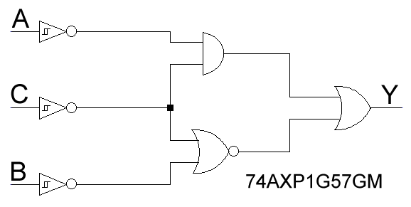
Configurable refers to the fact that this constellation of gates can be configured as an AND, NAND (with one inverting input), NOR, EXOR, NOT gate or non-inverting buffer. All inputs are Schmitt-trigger inputs. Here is the function table (from the datasheet):
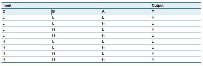
Currently there are three more devices in this family that only differ in the way how inputs and outputs are inverted or not.
Looking at all the possible 2-input gate configurations (AND, NOR, etc.) and imagining the two input signals not being static levels but as being two square wave signals where one has twice the frequency of the other (i.e. f and 2f), you will observe pulse width modulation or PWM. For instance, a 2-input AND gate with square waves of frequency f and 2f on its inputs will output a 25% duty-cycle signal with frequency f. Another example: when in the table above the input C remains high, and if A and B represent square wave signals (of frequency 2f and f respecticely), the output Y will be a 50% duty-cycle signal with frequency f. 75%, 0% and 100% duty-cycles are also possible.
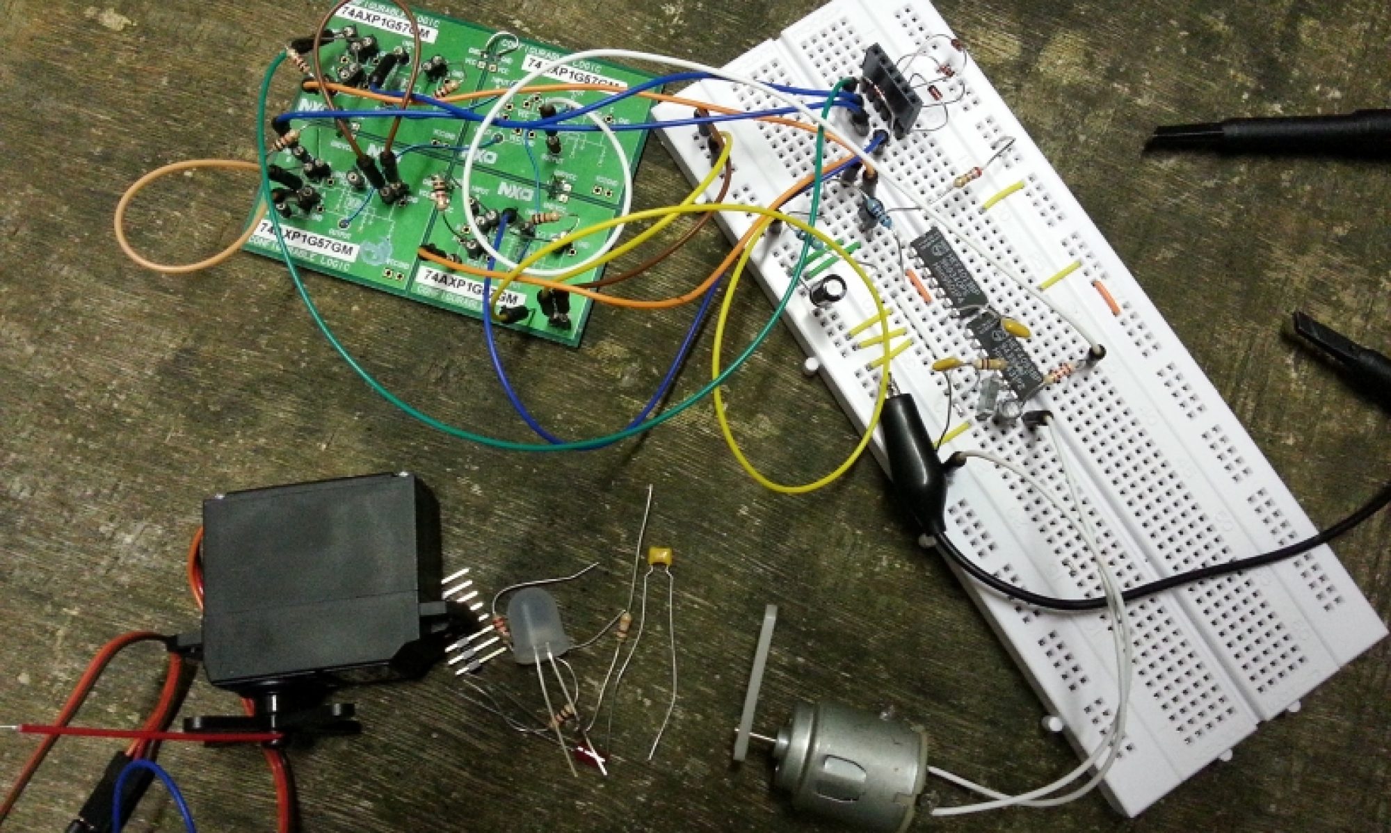
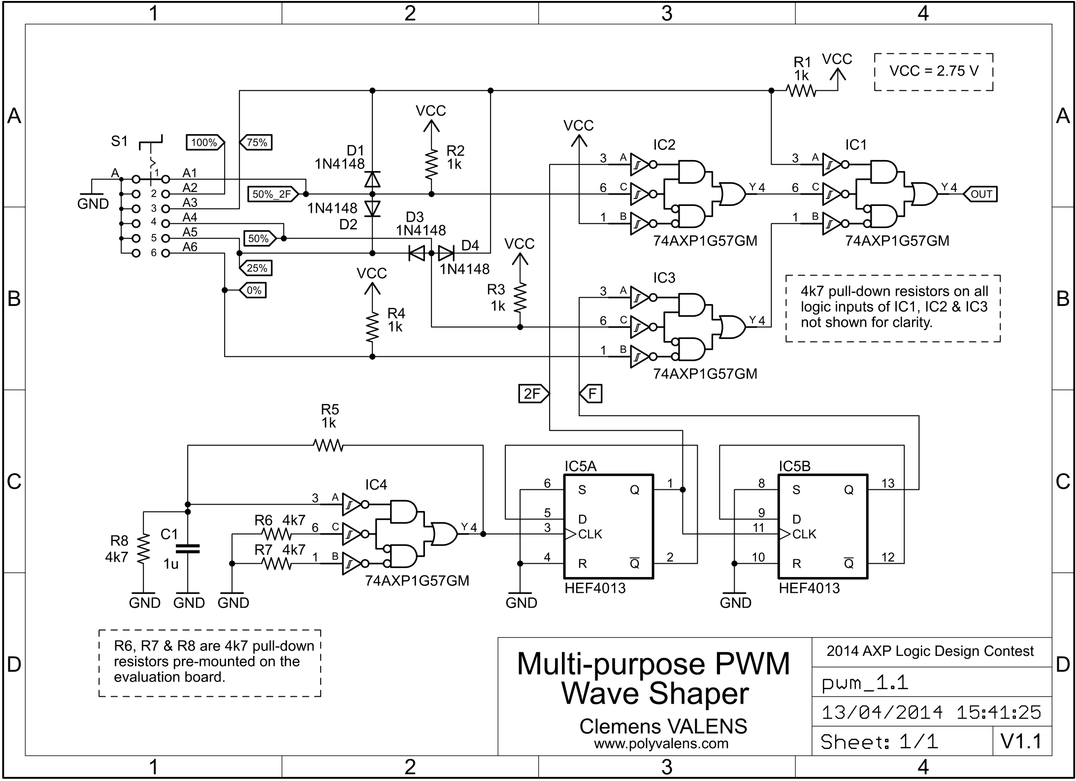
Based on this observation I designed a circuit using all four AXP chips and capable of producing a signal with a 0, 25, 50, 75 or 100% duty-cycle. Switching between the five signals is done with a single simple five-position switch. This means that the circuit has five inputs that each select a different duty-cycle.
The final circuit has some bonus options in the form of a sixth output signal, a 2f square wave (i.e. 50% duty-cycle), and an input priority scheme. This means that 75% has the highest, 25% comes second, then it is 50%, 0% and finally 100%. This will prove to be useful in the applications that follow.
Eagle 6.5.0 schematic (SCH) file
Eagle library (LBR) for the 74AXP1G57 device
(Note: These are XML files and will be opened by a browser. Use a right-click-save-as operation to download the files.)
To create the different duty-cycles, IC1 is reconfigured dynamically – by IC2 and IC3 – either as an AND gate (25%, input A=1, B=f and C=2f), a buffer (50%, A=1, B=f and C=1) or as a NAND gate (75%, A=0, B=f and C=2f). For the fast 50% signal IC1 functions also a buffer (A=1, B=1 and C=2f) but the signal to buffer is now on input C instead of on input B.
In the 0% and 100% modes IC1 is again in buffer mode (A=1 and C=1), passing the signal on its input B, but this signal is now forced by IC4 to either zero (0%) or one (100%).
IC2 is configured as a NAND gate, allowing on/off control of the 2f-signal.
IC3 switches between inverter and buffer allowing it to pass either the signal on its input A (inverter mode, C=0) or input B (buffer mode, C=1).
The four diodes help pulling down multiple logic gate inputs to activate the different modes.
The fourth AXP chip IC4 is wired as an oscillator to provide an input signal for the wave shaper. Because of the 4k7 pull-down resistors on the evaluation board that I did not want to remove, the feedback resistor has to be rather small. I found that 1k worked OK, but the signal produced was not very symmetrical. Since I had to divide it by two to create the f and 2f signals, I used the second D flip-flop of the 4013 to make the signal symmetrical before using it. So, the output of IC5A (pin 1) is the f signal, the output of IC5B (pin 13) is the 2f signal.
I powered everything from 2.75 V which is enough for the CMOS D flip-flop to function even though its datasheet recommends a minimum voltage of 3 V. The AXP logic can run from 3 V if needed, its absolute maximum supply voltage is 3.3 V according to the datasheet.
Here is a video showing the six different signals that can be generated with the circuit shown above.
Now you may wonder what such a circuit would be good for? Well, I have come up with the following list of applications, but I am convinced that there are more:
- 6-state LED blinker
- 5-speed motor control
- 5-level LED brightness control
- 3-position servo control
- 6-state input for microcontroller
- Student house doorbell multiplexer
- Two-channel two-wire long-distance cable connection with cable integrity indicator
Because of this list I have dubbed my circuit the “Multi-purpose PWM Wave Shaper”.
Six-state LED Blinker
If the frequency of the two input signals f and 2f is low enough, say less than 10 Hz, the circuit’s output signal is very well suited for controlling an LED in a visible way. The six possible modes are Off, 25%, 50%, 75%, On and Fast 50%. The first five modes can for instance be used to indicate the charge level of a battery when it is being charged, from empty to full. The 6th mode might indicate a fault condition. The video below shows the 6-state LED blinker.
Five-level LED Brightness Control
PWM is used often to control the brightness of an LED. Of course the multi-purpose PWM wave shaper can be used for this too. It will give you five levels of brightness. BTW, for good brightness control you need an exponential function, not linear. For every brightness step you should double the LED current. You can achieve this with this circuit by skipping the 75% mode: 0, 25, 50, 100, giving you four real levels of brightness.
The video shows what I mean.
Note that it is rather difficult to capture shining LEDs on video. So even though I used a red low-efficiency LED with (dimmed) background light, it still shows up as a rather bright whitish spot.
5-speed Motor Controller
PWM is also used a lot to control the speed of a motor. Of course the multi-purpose PWM wave shaper can be used for this too and it will give you five speeds. Interesting applications of such a speed controller are for instance toys, household equipement (for instance blender or hair dryer speed control) and simple electric vehicles.
Three-position RC Servo Control
RC model servos are controlled by variable width pulses. Usually a 1.5 ms pulse will move the servo to its center position. A longer pulse will move it further, a shorter pulse will move it less. The repetition rate or frequency of the pulse signal is not very important. A square wave with a frequency of 333 Hz has an on-time of 1.5 ms and can therefore be used to move a servo half way. The multi-purpose PWM wave shaper can not only deliver such a signal, it can also provide a 0.75 ms pulse (25%) or a 2.25 ms (75%) pulse, meaning that it can move the servo from the center position to the left or to the right.
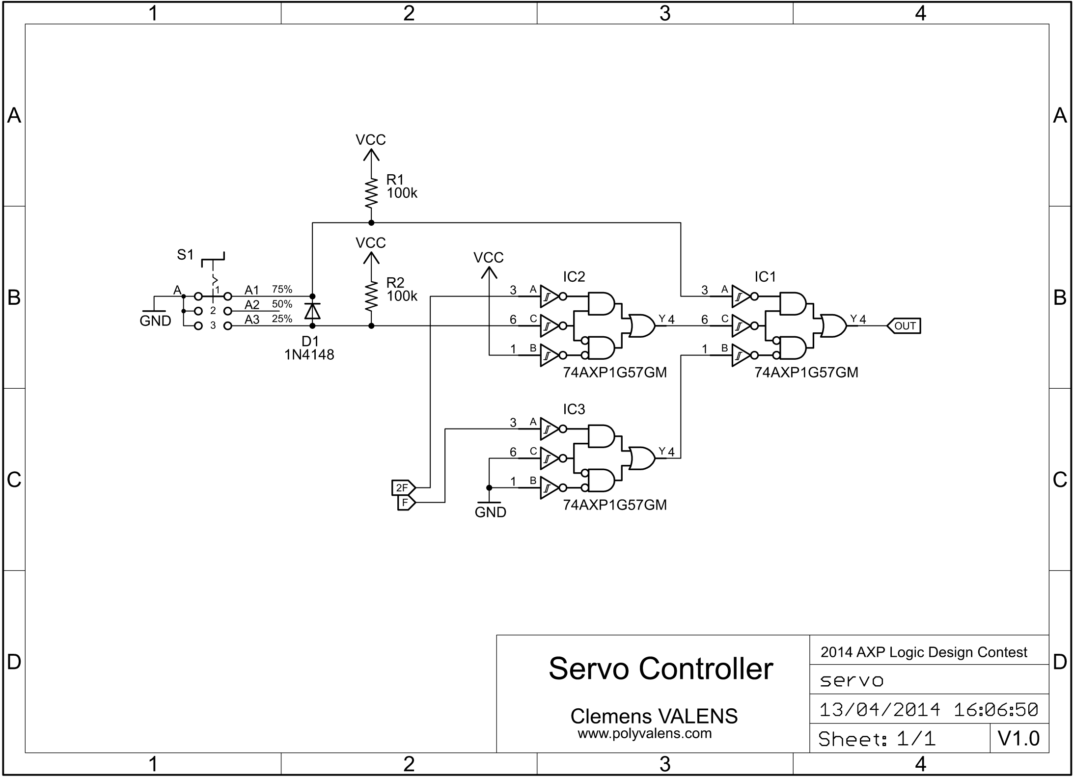
Using the input priority of the circuit we can fix the default or idle output signal to 50% (center), the left (25%) and right (75%) have higher priority and will override the center position signal, making the servo move. After releasing the left or right override signal, the servo will return to its home position. Such a servo control makes a good steering system for f.i. simple remote controlled electric toys.
If we fix the circuit’s default output to 0% or 100%, the servo will keep its last position when the 25%, 50% or 75% pulse signal is removed. This is useful in say car central locking systems.
This video shows the two modes of operation.
Together with the 5-speed motor controller you could make a cool drive-by-wire remote controlled toy vehicle for three-year olds.
When the servo controller is used in the return-to-home mode (default to 50%) the circuit can be simplified quite a bit as is shown in this drawing.
Eagle 6.5.0 schematic (SCH) file
Six-state Input For Microcontroller
In many microcontroler applications the number of GPIO pins is limited, making it sometimes impossible to connect all the pushbuttons you would like to and a compromise has to be found. Unless you add the multi-purpose PWM wave shaper to your circuit…
It is easy enough for a microcontroller to measure pulse lengths with enough precision to detect signals with 0, 25, 50, 75 and 100% duty cycles. Since a square wave signal with frequency 2f has a pulse length identical to a 25% duty-cycle signal with frequency f, such a signal can be detected as well, giving the microcontroller the capability of detecting six different states. When you reserve one of these states for the idle state, the microcontroller can detect key presses on five keys using only one GPIO pin.
Student House Doorbell Multiplexer
If you have ever shared a home with several other people, you may have known the doorbell chaos such a situation can create. Either every occupant has his or her own bell code or his or her own doorbell. In the first case the codes have to be published so the visitors know which code to use (resulting in ugly hard-to-read slips of paper being stuck next to the pushbutton), in the second case a doorbell has to be wired for each resident requiring lots of cables. The multi-purpose PWM wave shaper circuit can elegantly improve both situations for up to five persons.
To improve the first case, simply use the circuit as I did for the six-state LED blinker but replace the LED by a doorbell. The f frequency has to be low in order to create recognisable codes. All the residents share one doorbell, but respond to a different code.
To improve the second case, keep the f frequency high for improved response time and add a decoder circuit at the other end, something similar to the six-state input for microcontroller circuit. Each resident now gets his/her own doorbell and button.
In both cases the six-way selector switch at the circuit’s input is replaced by five pushbuttons because the sixth signal, the default 100% signal (or 0% if you add an inverting transistor) will be used to indicate the idle state.
The advantages of such a system are clear:
- no more codes to learn or figure out for visitors
- only one 3-wire cable from the door to the bell(s)

Two-channel two-wire long-distance cable connection with cable integrity indicator
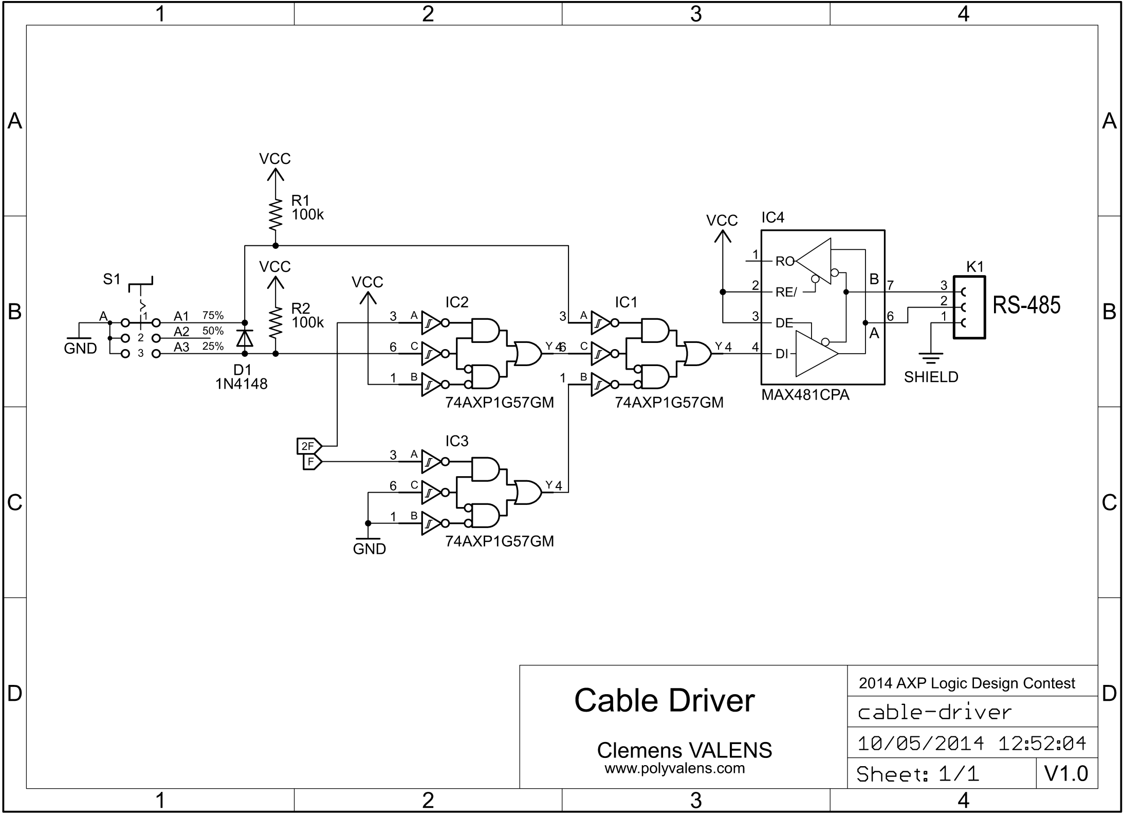
In some situations it may be necessary to connect a cable between a switch or sensor and a display system separated by a long distance. Long distance in this context is up to say 1 km, but by employing suitable cable drivers longer distances may be covered. Here I propose to use a RS-485 driver for transmitting the switch states over two wires. Since RS-485 uses differential signalling and because these drivers are designed for harsh environments they are well suited for driving long cables.
When we fix the multi-purpose PWM wave shaper’s idle position to a signal with a 50% duty-cycle and use the 25% and 75% duty-cycles to signal the switch states (on1, off, on2), we can use the 0% and 100% duty-cycles to indicate cable integrity. All we need is a PWM decoder similar to the ones used for the Student Doorbell or the Six-state Input for Microcontroller applications and off we go. The 0% signal can be used to indicate a shorted cable, while the 100% signal serves as a cut-cable indicator.
Here is the schematic for the long-distance cable driver. This is the same as the servo driver but with an RS-485 driver at its output.
Eagle 6.5.0 schematic (SCH) file
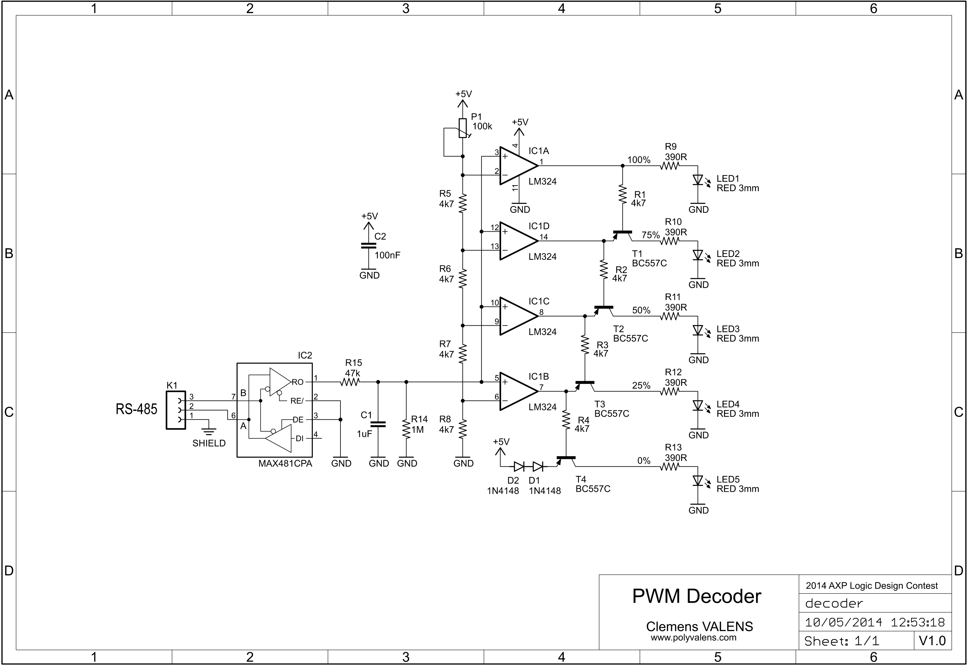
This is the circuit of the PWM decoder. With P1 you can set the sensitivity. Note that I did not draw any bus terminating resistors. Usually you would use 120 ohms for this.
Eagle 6.5.0 schematic (SCH) file
R15 and C1 extract the average value of the incoming PWM signal. This value is compared to four references created with the resistive voltage divider P1, R5-R8. Each comparator output switches the output just below it using a PNP transistor. This ensures that only one LED at a time will light up. The two diodes in the lowest level output (0%) compensate the voltage difference due to the LM324 not having rail-to-rail outputs. Without these diodes transistor T4 would never switch off.
During normal operation only the LEDs 2, 3 and 4 will light up. When the cable is damaged the RS-485 driver will either output a stable high level (open inputs, this will happen in most cases) or, depending on the selected driver, an undefined sequence of high and low levels (when input A equals B). These error conditions will be visualised by LED1 and LED5.
Why Not Use a Microcontroller Instead?
Of course most of the applications described above can be solved with a small microcontroller, but doing it the “discrete” way has some advantages:
- No program to write, port, compile, flash and maintain
- Discrete logic can work at much higher frequencies
- It is easy to create an IC for this circuit, making it cheap and small.
The second advantage can also be attained by using an FPGA, but that introduces the first disadvantage of programming.
Extending the Circuit
An interesting extension may be the addition of a 4f (or 0.5f) signal to allow finer-grained control of the duty-cycle. But trying to do too much with discrete gates is not a good idea, it may simply be faster and/or cheaper to switch to a microcontroller or FPGA based circuit instead.
Sounding off
That’s it for this entry. I hope you enjoyed reading it and I hope that it has been of some use to you. If you come up with any new applications for this multi-purpose PWM wave shaper circuit, please let me know.
(c) Clemens Valens, April 2014